Beranda
/ Diy Solar Tracker Circuit : Simple Solar Tracker System Mechanism And Working Homemade Circuit Projects : Pcb layout on desktop fig:
Diy Solar Tracker Circuit : Simple Solar Tracker System Mechanism And Working Homemade Circuit Projects : Pcb layout on desktop fig:
Insurance Gas/Electricity Loans Mortgage Attorney Lawyer Donate Conference Call Degree Credit Treatment Software Classes Recovery Trading Rehab Hosting Transfer Cord Blood Claim compensation mesothelioma mesothelioma attorney Houston car accident lawyer moreno valley can you sue a doctor for wrong diagnosis doctorate in security top online doctoral programs in business educational leadership doctoral programs online car accident doctor atlanta car accident doctor atlanta accident attorney rancho Cucamonga truck accident attorney san Antonio ONLINE BUSINESS DEGREE PROGRAMS ACCREDITED online accredited psychology degree masters degree in human resources online public administration masters degree online bitcoin merchant account bitcoin merchant services compare car insurance auto insurance troy mi seo explanation digital marketing degree floridaseo company fitness showrooms stamfordct how to work more efficiently seowordpress tips meaning of seo what is an seo what does an seo do what seo stands for best seotips google seo advice seo steps, The secure cloud-based platform for smart service delivery. Safelink is used by legal, professional and financial services to protect sensitive information, accelerate business processes and increase productivity. Use Safelink to collaborate securely with clients, colleagues and external parties. Safelink has a menu of workspace types with advanced features for dispute resolution, running deals and customised client portal creation. All data is encrypted (at rest and in transit and you retain your own encryption keys. Our titan security framework ensures your data is secure and you even have the option to choose your own data location from Channel Islands, London (UK), Dublin (EU), Australia.
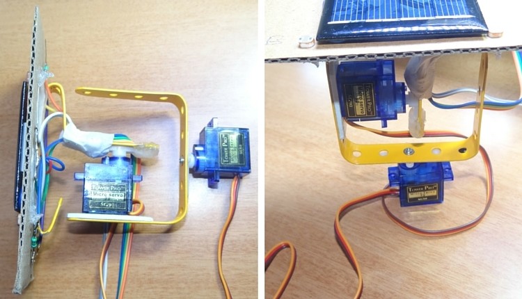
Diy Solar Tracker Circuit : Simple Solar Tracker System Mechanism And Working Homemade Circuit Projects : Pcb layout on desktop fig:. In this project i will show you how to create a solar tracker which like the name implies can follow the movement of the sun throughout the day. At maximum, the solar tracker is perpendicular to the light source. This diy solar tracker system circuit is useful for maintaing the right angle of the solar panels to the sun and maximize the harvested power. The device is able to track the daytime motion of the sun precisely and shift in the vertical axis accordingly. Pcb layout on desktop fig:
This single axis tracker circuit finds the sun at dawn, follows the sun during the day, and resets for the next day. I would like to have this in differential mode utilizing both the photodiode in one amplifier. And at the end i will show you the energy harvest difference between a solar tracker mounted solar panel… Level and tighten ground nuts. The circuit design of solar tracker is simple but setting up the system must be done carefully.
How To Build A Diy Solar Sun Tracker Using Arduino Projects from v6f7u6f8.rocketcdn.me The device is able to track the daytime motion of the sun precisely and shift in the vertical axis accordingly. I would like to have this in differential mode utilizing both the photodiode in one amplifier. Circuit implementation of dual axis solar tracker system. The solar tracker is made for easy assembly. The circuit design of solar tracker is simple but setting up the system must be done carefully. It ought to be mentioned that two sets of the above described circuit assemblies is going to be essential to managing the dual measures or simply just to create the above mentioned dual tracker solar system mechanism. The solar tracker circuit uses a window comparator to maintain the motor in a idle state as long as the two ldrs are under the same illumination level. This web site shows how i did it.
The solar tracker is made for easy assembly.
Here is a simple low cost solar tracker circuit which automatically moves the solar panel in the direction of sun. The circuit and the mechanism explained in this article may be considered as the easiest and perfect dual axis solar tracker system. Solar tracker circuit schematic simple diy solar tracker system schematic The solar tracker is made for easy assembly. The pwm inputs of two servos are given from digital pins 9 and 10 of arduino. A tia (trans impedance amplifier) is also utilized to obtain higher bandwidths. Dual axis solar tracker project is to provide an efficient solar distributed generation system. Take a look at the installation manual. This web site shows how i did it. R3 = 15k, r4 = 39k, p1 = 100k, p2 = 22k, ldr = normal type with a resistance of around 10 k to 40k in daylight under. The produced electrical energy can be increased if we move the solar panel as the movement of the sun. Using a tia (as per the linked circuit) is mainly done when you want to keep the current output from the photodiode (more) linear with incident light power. In this arduino solar panel tracker , arduino is powered by the 9v battery and all the other parts are powered by the arduino.
As you can see the circuit is very simple and can easily be built with help of a small breadboard. This single axis tracker circuit finds the sun at dawn, follows the sun during the day, and resets for the next day. Solar power is one of the most accessible types of renewable energy and is rapidly increasing in efficiency and affordability. Circuit implementation of dual axis solar tracker system. Solar energy panels best solar panels solar tracker 12 volt led solar charger panel systems solar energy system sustainable energy diy solar.
Arduino Solar Tracker from www.electronicshub.org Buck mode switching regulator for solar applications. The two ldrs are placed into tubes side by side, mounted onto the solar panel. I had seen other solar panel tracking systems on the web based on antenna rotators. The final result is a sturdy, inexpensive alternative to the costly solar trackers you can buy. Using a tia (as per the linked circuit) is mainly done when you want to keep the current output from the photodiode (more) linear with incident light power. Solar cell nicad charger using maxim max639: Mppt stands for maximum power point tracker, which is an electronic system designed for optimizing the varying power output from a solar panel module such that the connected battery exploits the maximum available power from the solar panel. This system can track the sun all day long, can be used for harvesting 15% more energy than typical static solar plates.
Generally solar panels are stationary devices which is fixed at a position.
The two ldrs are placed into tubes side by side, mounted onto the solar panel. I will make a schematic, a prototype printed circuit board and arduino sketch free. In this project i will show you how to create a solar tracker which like the name implies can follow the movement of the sun throughout the day. Circuit of solar tracking system. Solar power is one of the most accessible types of renewable energy and is rapidly increasing in efficiency and affordability. Dual axis solar tracker project is to provide an efficient solar distributed generation system. A tia (trans impedance amplifier) is also utilized to obtain higher bandwidths. R3 = 15k, r4 = 39k, p1 = 100k, p2 = 22k, ldr = normal type with a resistance of around 10 k to 40k in daylight under. Led7 solar tracker circuit diagram: The complete circuit diagram for the solar tracking arduino project is shown below. Today this circuit used in modern solar street light and solar systems in homes for increasin. The circuit design for the system would be: Solar cell nicad charger using maxim max639:
A tia (trans impedance amplifier) is also utilized to obtain higher bandwidths. Pcb layout on desktop fig: It is based on a solar tracker that can rotate automatically to track the sun with the help of four ldr sensors and two servomotors (sm1 and sm2), or manually using a potentiometer. The solar tracker 2 circuit kit (catalog #st2) from mtm scientific contains all the electrical parts you need to build a circuit which will automatically find and follow the sun across the sky. Circuit implementation of dual axis solar tracker system.
Arduino Solar Tracker Arduino Project Hub from hacksterio.s3.amazonaws.com It is based on a 1960s vintage tv antenna rotator, driven by 21st century microcontroller technology. Circuit of solar tracking system. The circuit design for the system would be: A tia (trans impedance amplifier) is also utilized to obtain higher bandwidths. The circuit is for one axis, if you want two axis use this circuit twice.thanks for watching, don't forget to like and subscribedownload the image here: Using a tia (as per the linked circuit) is mainly done when you want to keep the current output from the photodiode (more) linear with incident light power. As you can see the circuit is very simple and can easily be built with help of a small breadboard. At maximum, the solar tracker is perpendicular to the light source.
The solar tracker data can be viewed on a smartphone, iphone, ipad and any other items with internet connection.
The circuit is for one axis, if you want two axis use this circuit twice.thanks for watching, don't forget to like and subscribedownload the image here: Take a look at the installation manual. The ldrs are arranged on the solar panel in such a way to strike the radiation on ldrs, directly from the sun. I will make a schematic, a prototype printed circuit board and arduino sketch free. It was pretty easy to build. The final result is a sturdy, inexpensive alternative to the costly solar trackers you can buy. The produced electrical energy can be increased if we move the solar panel as the movement of the sun. The solar tracker circuit uses a window comparator to maintain the motor in a idle state as long as the two ldrs are under the same illumination level. Level and tighten ground nuts. This system can track the sun all day long, can be used for harvesting 15% more energy than typical static solar plates. Pcb layout on desktop fig: The complete circuit diagram for the solar tracking arduino project is shown below. In this sun tracker circuit, two ldrs are used to detect the direction of sun.